Automating Manufacturing Systems with PLCs
Control engineering has evolved over time. In the past humans were the mainmethod for controlling a system. More recently electricity has been used for control andearly electrical control was based on relays. These relays allow power to be switched on and off without a mechanical switch. It is common to use relays to make simple logicalcontrol decisions. The development of low cost computer has brought the most recent revolution,the Programmable Logic Controller (PLC). The advent of the PLC began in the1970s, and has become the most common choice for manufacturing controls.PLCs have been gaining popularity on the factory floor and will probably remainpredominant for some time to come. Most of this is because of the advantages they offer.
1.1 Ladder logic
Ladder logic is the main programming method used for PLCs. As mentioned before, ladder logic has been developed to mimic relay logic. logic diagrams was a strategic one. By selecting ladder logic as the main programming method, the amount of retraining needed for engineers and tradespeople was greatly reduced.
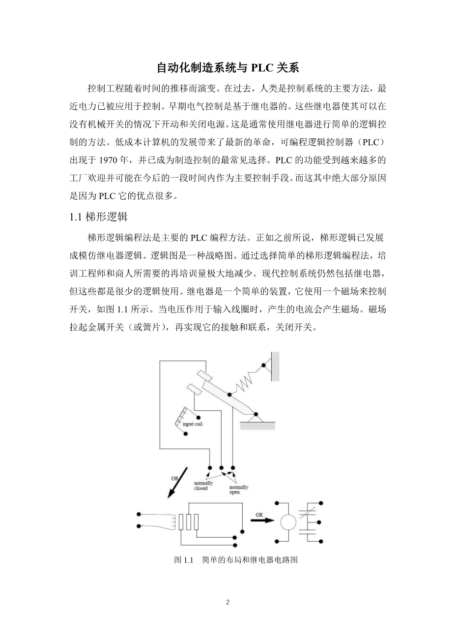
Modern control systems still include relays, but these are rarely used for logic. A relay is a simple device that uses a magnetic field to control a switch, as pictured in Figure 1.1. When a voltage is applied to the input coil, the resulting current creates a magnetic field. The magnetic field pulls a metal switch (or reed) towards it and the contacts touch, closing the switch.
Figure 1.1 Simple Relay Layouts and Schematics
Relays are used to let one power source close a switch for another (often high current) power source, while keeping them isolated. An example of a relay in a simple control application is shown in Figure 1.2. In this system the first relay on the left is used as normally closed, and will allow current to flow until a voltage is applied to the input A. The second relay is normally open and will not allow current to flow until a voltage is applied to the input B. If current is flowing through the first two relays then current will flow through the coil in the third relay, and close the switch for output C. This circuit would normally be drawn in the ladder logic form. This can be read logically as C will be on if A is off and B is on.
Figure 1.2 A Simple Relay Controller
The example in Figure 1.2 does not show the entire control system, but only the logic. When we consider a PLC there are inputs, outputs, and the logic. Figure 1.3 shows a more complete representation of the PLC. Here there are two inputs from push buttons.We can imagine the inputs as activating 24V DC relay coils in the PLC. This in turn drives an output relay that switches 115V AC, that will turn on a light. Note, in actual PLCs inputs are never relays, but outputs are often relays. The ladder logic in the PLC is actually a computer program that the user can enter and change. Notice that both of the input push buttons are normally open, but the ladder logic inside the PLC has one normally open contact, and one normally closed contact. Do not think that the ladder logic in the PLC need so match the inputs or outputs. Many beginners will get caught trying to make the ladder logic match the input types.
.
Figure 1.3 A PLC Illustrated With Relays
Many relays also have multiple outputs (throws) and this allows an output relay to also be an input simultaneously. The circuit shown in Figure 1.4 is an example of this, it is called a seal in circuit. In this circuit the current can flow through either branch of the circuit, through the contacts labelled A or B. The input B will only be on when the output B is on. If B is off, and A is energized, then B will turn on. If B turns on then the input B will turn on, and keep output B on even if input A goes off. After B is turned on the output B will not turn off.
Figure 1.4 A Seal-in Circuit
1.2 Programming
The first PLCs were programmed with a technique that was based on relay logic wiring schematics. This eliminated the need to teach the electricians, technicians and engineers how to program a computer - but, this method has stuck and it is the most common technique for programming PLCs today. An example of ladder logic can be seen in Figure 1.5. To interpret this diagram imagine that the power is on the vertical line on the left hand side, we call this the hot rail. On the right hand side is the neutral rail. In the figure there are two rungs, and on each rung there are combinations of inputs (two vertical lines) and outputs (circles). If the inputs are opened or closed in the right combination the power can flow from the hot rail, through the inputs, to power the outputs, and finally to the neutral rail. An input can come from a sensor, switch, or any other type of sensor. An output will be some device outside the PLC that is switched on or off, such as lights or motors. In the top rung the contacts are normally open and normally closed. Which means if input A is on and input B is off, then power will flow through the output and activate it. Any other combination of input values will result in the output X being off.
Figure 1.5 A Simple Ladder Logic Diagram
The second rung of Figure 1.5 is more complex, there are actually multiple combinations of inputs that will result in the output Y turning on. On the left most part of the rung, power could flow through the top if C is off and D is on. Power could also (and simultaneously) flow through the bottom if both E and F are true. This would get power half way across the rung, and then if G or H is true the power will be delivered to output Y. In later chapters we will examine how to interpret and construct these diagrams.
There are other methods for programming PLCs. One of the earliest techniques involved mnemonic instructions. These instructions can be derived directly from the ladder logic d
剩余内容已隐藏,支付完成后下载完整资料
英语译文共 12 页,剩余内容已隐藏,支付完成后下载完整资料
资料编号:[606156],资料为PDF文档或Word文档,PDF文档可免费转换为Word